
Capacity design (AISC)
1 New project
Launch IDEA StatiCa (download the newest version) and open the source project file. The joint design is finished, and it is prepared for the standard Stress/Strain analysis.
2 Calculation and check
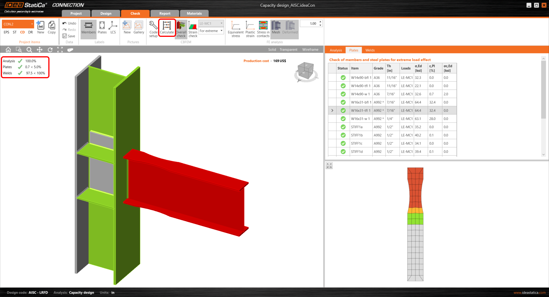
Start the stress/strain analysis by the Calculate button in the ribbon. The analysis model is automatically generated, the calculation is performed, and you can see the overall check results in the left top corner of the scene.

You can see that based on the stress/strain analysis, the joint is well designed and passed all the checks.
To keep these results, copy this project item.

3 Capacity check
In the new project item (CON2), change the analysis type to CD – Capacity design.

The dissipative item has to be selected. It can be added by the command from the top ribbon or by the mouse right-click in the tree in the scene.

A member or a plate where a plastic hinge is expected to occur should be chosen as a dissipative item. The material overstrength factor and strain-hardening factor are applied to the chosen item. In this example, select the member W16x31 as the dissipative item and confirm the selection with the spacebar/enter key/right-click.

In the properties Members, the parameters of W16x31 have to be adjusted: Set the Model type to N-Vz-My, because the connection resists the bending moment in the vertical plane only and bending around the minor beam axis must be restrained.
Switch the Forces in parameter to Position, because then the exact acting force position can be defined. The position of the plastic hinge is similar to the position of the acting force: X = 17 inch.

How to know the right position of the plastic hinge? The engineer needs to decide where it will occur. Usually, the plastic hinge is determined in the beam. In this example, it will occur in the middle of the dog bone operation. It’s handy to read the position from the application (wireframe view).

In the next step, the load effects have to be defined. Loads for seismic analysis are code dependent (the material overstrength factor, strain-hardening factor) and influenced also by yield strength, geometrical characteristic of the cross-section, etc.
Loads for this example were calculated by this procedure:
My = Cpr .Ry .Fy .Zpl,y(RBS) and corresponding shear force Vz = –2 My / Lh, where:
- Ry – ratio of probable to minimal yield strength – AISC 341-16 – Table A3.1; for A992 – Ry = 1.1
- \( C_{pr}=\frac{F_y+F_u}{2\cdot F_y} \le 1.2 \) – strain-hardening factor; for A992 – Cpr = 1.15
- Fy – characteristic yield strength; for A992 – Fy = 50.0 ksi
- Fu – characteristic ultimate strength; for A992 – Fu = 65.0 ksi
- Zpl,y(RBS) – plastic section modulus; value for reduced beam section – Zpl,y,(RBS) = 44.80 in3
- Lh – distance between plastic hinges on the beam; Lh = 250 - (2 . 17) = 216 in
My = 1.15 x 1.1 x 50 x 44.80 = 2834 kip.in


\[ V_{\textrm{Ed}} = \frac{2 \cdot M_{\textrm{y}}}{L_{h}} = 2 \cdot \frac{2834}{216} = 26,2 \, \textrm{kip} \]
Add the calculated shear force and bending moment as a new Load effect (LE).

The shear force and bending moment must be with appropriate signs so that the bending moment is decreasing on the beam in the direction away from the node.
Now the capacity analysis can be started by the Calculate command.

You can see from the results that the joint didn’t pass the code check. Some changes in design are required.
We can start by adding 4 stiffeners into the column aligned according to the beam flanges. Set the thickness of the stiffeners to 1/2".

To increase column load capacity, add a one-sided doubler to its web (add Stiffening plate manufacturing operation).

The stiffeners at the column web need to be cut and welded to the doublers by the Cut of the plate manufacturing operation.

Repeat the cut of the plate to connect the other front stiffener to the doublers.
All design actions are done now, run Calculate in the Check tab. You can see that all components (like welds and bolts) passed the code-check. The plastic strain of the dissipative item plates does not influence overall results.
The occurrence of the plastic hinge can be explored in the Plastic strain analysis window.
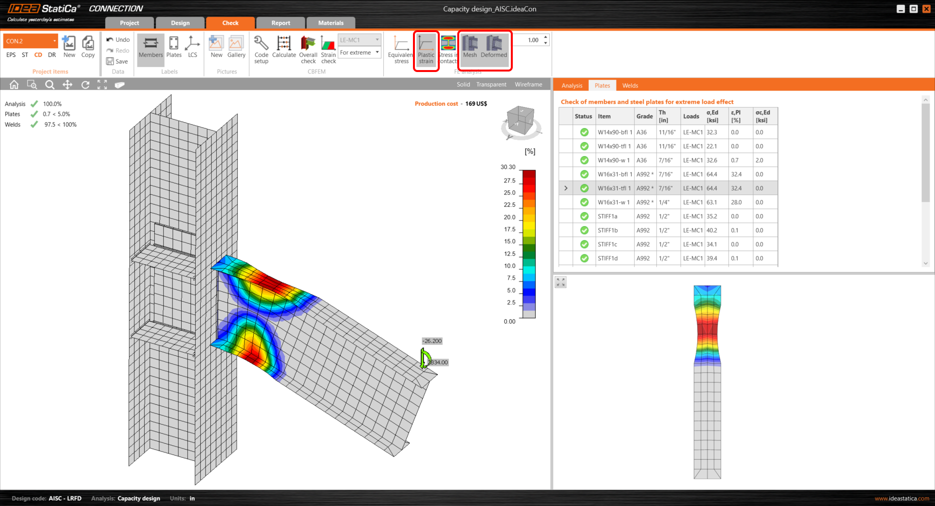
The plastic hinge appeared at the expected location and this joint passed the checks required by the capacity design.
For a better understanding of the results, see the Theoretical Background.
4 Report
At last, you can review the Report. IDEA StatiCa offers a fully customizable report to print out or save in an editable format.

You have performed a capacity design check of a structural steel joint according to American standards (AISC).
Resistance factors
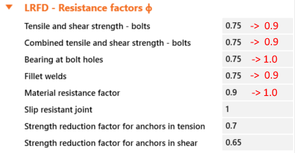
In case that design requirements for 'prequalified' connection are respected and the available strengths are calculated in accordance with AISC 358-16, resistance factors ϕ shall be taken as follows:
For ductile limit states ϕd = 1.00
For nonductile limit states ϕn = 0.90
In this case, these factors shall be edited in IDEA Connection 'Code setup':

Special moment frames
For special moment frames designed in accordance with AISC 358-16 the prescribed detailing should be followed. Check of this detailing isn't included in IDEA StatiCa Connection code check and it has to be evaluated independently.
Protected zone
A protected zone shall be defined for each prequalified connection. Unless otherwise specifically indicated in the used Standard, the protected zone of the beam shall be defined as the area from the face of the column flange to one-half of the beam depth beyond the plastic hinge.

Bolts and welds shall be avoided in the protected zone if the connection isn't detailed in accordance with the individual provisions of AISC 358-16.