IDEA StatiCa Detail – Structural design of concrete discontinuities
The theoretical background is based on COMPATIBLE STRESS FIELD DESIGN OF STRUCTURAL CONCRETE
(Kaufmann et al., 2020)
Structural design of concrete discontinuities in IDEA StatiCa Detail
General introduction for the structural design of concrete details
Main assumptions and limitations
Reinforcement structural design
Finite element implementation in IDEA StatiCa Detail
- Supports and load transmitting components
- Load transfer at trimmed ends of beams
- Geometric modification of cross-sections
- Finite element types
- Meshing
- Solution method and load-control algorithm
- Presentation of results
Structural element verification in IDEA StatiCa Detail
Verification of the structural concrete elements (EN)
- Material models
- Safety factors
- Ultimate limit state analysis
- Partially loaded areas (PLA)
- Serviceability limit state analysis
General introduction for the structural design of concrete details
The design and assessment of concrete elements are normally performed at the sectional (1D-element) or point (2D-element) level. This procedure is described in all standards for structural design, e.g., in (EN 1992-1-1), and it is used in everyday structural engineering practice. However, it is not always known or respected that the procedure is only acceptable in areas where Bernoulli-Navier hypothesis of plane strain distribution applies (referred to as B-regions). The places where this hypothesis does not apply are called discontinuity or disturbed regions (D-Regions). Examples of B and D regions of 1D-elements are given in (Fig. 1). These are, e.g., bearing areas, parts where concentrated loads are applied, locations where an abrupt change in the cross-section occurs, openings, etc. When designing concrete structures, we meet a lot of other D-Regions such as walls, bridge diaphragms, corbels, etc.
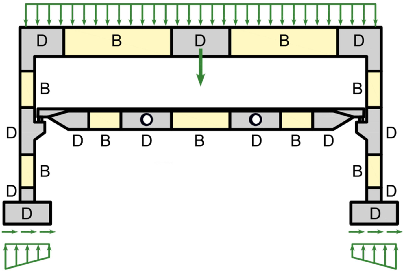
\[ \textsf{\textit{\footnotesize{Fig. 1\qquad Discontinuity regions (Navrátil et al. 2017)}}}\]
In the past, semi-empirical design rules were used for dimensioning discontinuity regions. Fortunately, these rules have been largely superseded over the past decades by strut-and-tie models (Schlaich et al., 1987) and stress fields (Marti 1985), which are featured in current design codes and frequently used by designers today. These models are mechanically consistent and powerful tools. Note that stress fields can generally be continuous or discontinuous and that strut-and-tie models are a special case of discontinuous stress fields.
Despite the evolution of computational tools over the past decades, Strut-and-Tie models are essentially still used as hand calculations. Their application for real-world structures is tedious and time-consuming since iterations are required, and several load cases need to be considered. Furthermore, this method is not suitable for verifying serviceability criteria (deformations, crack widths, etc.).
The interest of structural engineers in a reliable and fast tool to design D-regions led to the decision to develop the new Compatible Stress Field Method, a method for computer-aided stress field design that allows the automatic design and assessment of structural concrete members subjected to in-plane loading.
The Compatible Stress Field Method is a continuous FE-based stress field analysis method in which classic stress field solutions are complemented with kinematic considerations, i.e., the state of strain is evaluated throughout the structure. Hence, the effective compressive strength of concrete can be automatically computed based on the state of transverse strain in a similar manner as in compression field analyses that account for compression softening (Vecchio and Collins 1986; Kaufmann and Marti 1998) and the EPSF method (Fernández Ruiz and Muttoni 2007). Moreover, the CSFM considers tension stiffening, providing realistic stiffnesses to the elements, and covers all design code prescriptions (including serviceability and deformation capacity aspects) not consistently addressed by previous approaches. The CSFM uses common uniaxial constitutive laws provided by design standards for concrete and reinforcement. These are known at the design stage, which allows the partial safety factor method to be used. Hence, designers do not have to provide additional, often arbitrary material properties as are typically required for non-linear FE-analyses, making the method perfectly suitable for engineering practice.
To foster the use of computer-aided stress fields by structural engineers, these methods should be implemented in user-friendly software environments. To this end, the CSFM has been implemented in IDEA StatiCa Detail; a new user-friendly commercial software developed jointly by ETH Zurich and the software company IDEA StatiCa in the framework of the DR-Design Eurostars-10571 project.
Reinforcement structural design
Workflow and goals
The goal of reinforcement design tools in the CSFM is to help designers determine the location and required amount of reinforcing bars efficiently. The following tools are available to help/ guide the user in this process: linear calculation, topology optimization, and area optimization.
Reinforcement design tools consider more simplified constitutive models than the models used for the final verification of the structure. Therefore, the definition of the reinforcement in this step should be considered a pre-design to be confirmed/refined during the final verification step. The use of the different reinforcement design tools will be depicted on the model shown in Fig. 5, which consists of one end of a simply supported beam with variable depth subjected to a uniformly distributed load.
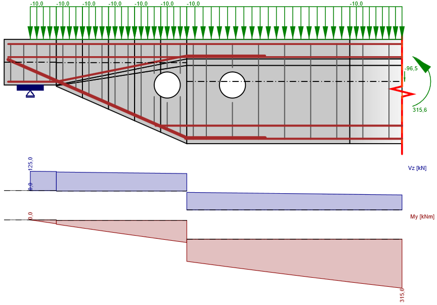
\[ \textsf{\textit{\footnotesize{Fig. 5\qquad Model used to illustrate the use of the reinforcement design tools.}}}\]
Reinforcement locations
For regions where the reinforcement layout is not known beforehand, there are two methods available in the CSFM to help the user determine the optimum location of reinforcing bars: linear analysis and topology optimization. Both tools provide an overview of the location of tensile forces in the uncracked region for a certain load case.
Linear analysis
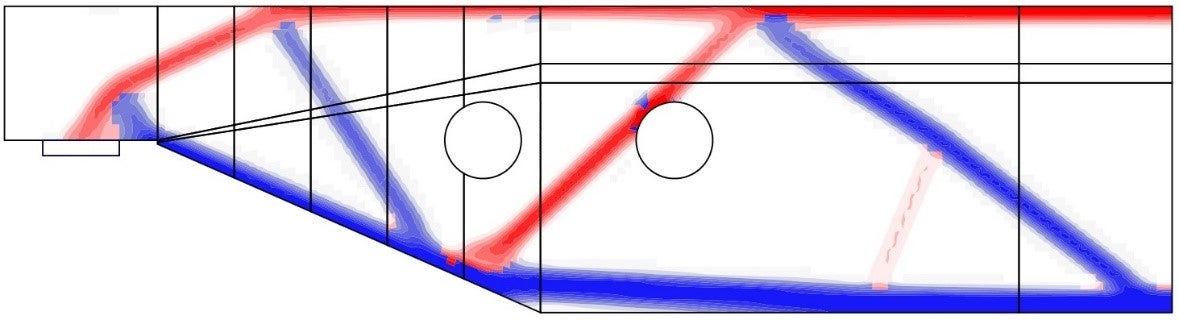
The linear analysis considers linear elastic material properties and neglects reinforcement in the concrete region. It is, therefore, a very fast calculation that provides a first insight into the locations of tension and compression areas. An example of such a calculation is shown in Fig. 6.
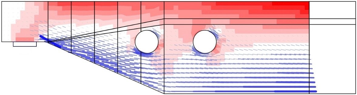
\[ \textsf{\textit{\footnotesize{Fig. 6\qquad Results from the linear analysis tool for defining reinforcement layout}}}\]
\[ \textsf{\textit{\footnotesize{(red: areas in compression, blue: areas in tension).}}}\]
Topology optimization
Topology optimization is a method that aims to find the optimal distribution of material in a given volume for a certain load configuration. The topology optimization implemented in Idea StatiCa Detail uses a linear finite element model. Each finite element may have a relative density from 0 to 100 %, representing the relative amount of material used. These element densities are the optimization parameters in the optimization problem. The resulting material distribution is considered optimal for the given set of loads if it minimizes the total strain energy of the system. By definition, the optimal distribution is also the geometry that has the largest possible stiffness for the given loads.
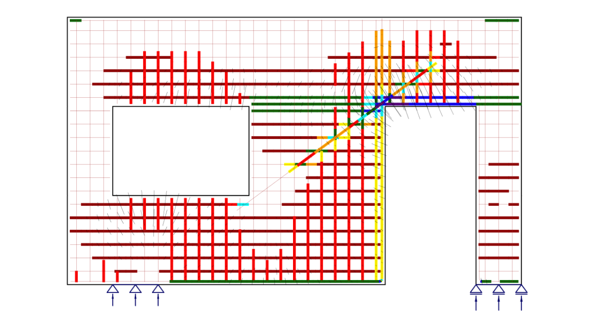
The iterative optimization process starts with a homogeneous density distribution. The calculation is performed for multiple total volume fractions (20%, 40%, 60% and 80%), which allows the user to select the most practical result, as proposed by . The resulting shape consists of trusses with struts and ties and represents the optimum shape for the given load cases (Fig. 7).
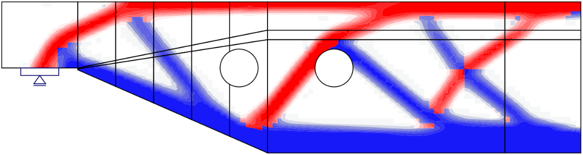
\[ \textsf{\textit{\footnotesize{Fig. 7\qquad Results from the topology optimization design tool with 20\% and 40\% effective volume}}}\]
\[ \textsf{\textit{\footnotesize{(red: areas in compression, blue: areas in tension).}}}\]
Finite element implementation in IDEA StatiCa Detail
Introduction
The CSFM considers continuous stress fields in the concrete (2D finite elements), complemented by discrete “rod” elements representing the reinforcement (1D finite elements). Therefore, the reinforcement is not diffusely embedded into the concrete 2D finite elements, but explicitly modeled and connected to them. A plane stress state is considered in the calculation model.
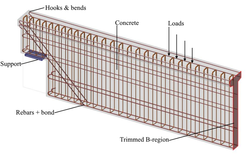
\[ \textsf{\textit{\footnotesize{Fig. 8\qquad Visualization of the calculation model of a structural element (trimmed beam) in Idea StatiCa Detail.}}}\]
Both entire walls and beams, as well as details (parts) of beams (isolated discontinuity region, also called trimmed end), can be modeled. In the case of walls and entire beams, supports must be defined in such a way that an (externally) isostatic (statically determinate) or hyperstatic (statically indeterminate) structure results. The load transfer at the trimmed ends of beams is introduced by means of a special Saint-Venant transfer zone (described in Section 3.3), which ensures a realistic stress distribution in the analyzed detail region.
References
ACI Committee 318. 2009a. Building Code Requirements for Structural Concrete (ACI 318-08) and Commentary. Farmington Hills, MI: American Concrete Institute.
Alvarez, Manuel. 1998. Einfluss des Verbundverhaltens auf das Verformungsvermögen von Stahlbeton. IBK Bericht 236. Basel: Institut für Baustatik und Konstruktion, ETH Zurich, Birkhäuser Verlag.
Beeby, A. W. 1979. “The Prediction of Crack Widths in Hardened Concrete.” The Structural Engineer 57A (1): 9–17.
Broms, Bengt B. 1965. “Crack Width and Crack Spacing In Reinforced Concrete Members.” ACI Journal Proceedings 62 (10): 1237–56. https://doi.org/10.14359/7742.
Burns, C.. 2012. “Serviceability Analysis of Reinforced Concrete Members Based on the Tension Chord Model.” IBK Report Nr. 342, Zurich, Switzerland: ETH Zurich.
Crisfield, M. A. 1997. Non-Linear Finite Element Analysis of Solids and Structures. Wiley.
European Committee for Standardization (CEN). 2015. 1 Eurocode 2: Design of concrete structures - Part 1-1: General rules and rules for buildings. Brussels: CEN, 2005.
Fernández Ruiz, M., and A. Muttoni. 2007. “On Development of Suitable Stress Fields for Structural Concrete.” ACI Structural Journal 104 (4): 495–502.
Kaufmann, W., J. Mata-Falcón, M. Weber, T. Galkovski, D. Thong Tran, J. Kabelac, M. Konecny, J. Navratil, M. Cihal, and P. Komarkova. 2020. “Compatible Stress Field Design Of Structural Concrete. Berlin, Germany.”AZ Druck und Datentechnik GmbH, ISBN 978-3-906916-95-8.
Kaufmann, W., and P. Marti. 1998. “Structural Concrete: Cracked Membrane Model.” Journal of Structural Engineering 124 (12): 1467–75. https://doi.org/10.1061/(ASCE)0733-9445(1998)124:12(1467).
Kaufmann, W.. 1998. “Strength and Deformations of Structural Concrete Subjected to In-Plane Shear and Normal Forces.” Doctoral dissertation, Basel: Institut für Baustatik und Konstruktion, ETH Zürich. https://doi.org/10.1007/978-3-0348-7612-4.
Konečný, M., J. Kabeláč, and J. Navrátil. 2017. Use of Topology Optimization in Concrete Reinforcement Design. 24. Czech Concrete Days (2017). ČBS ČSSI. https://resources.ideastatica.com/Content/06_Detail/Verification/Articles/Topology_optimization_US.pdf.
Marti, P. 1985. “Truss Models in Detailing.” Concrete International 7 (12): 66–73.
Marti, P. 2013. Theory of Structures: Fundamentals, Framed Structures, Plates and Shells. First edition. Berlin, Germany: Wiley Ernst & Sohn.
http://sfx.ethz.ch/sfx_locater?sid=ALEPH:EBI01&genre=book&isbn=9783433029916.
Marti, P., M.Alvarez, W. Kaufmann, and V. Sigrist. 1998. “Tension Chord Model for Structural Concrete.” Structural Engineering International 8 (4): 287–298.
https://doi.org/10.2749/101686698780488875.
Mata-Falcón, J. 2015. “Serviceability and Ultimate Behaviour of Dapped-End Beams (In Spanish: Estudio Del Comportamiento En Servicio y Rotura de Los Apoyos a Media Madera).” PhD thesis, Valencia: Universitat Politècnica de València.
Meier, H. 1983. “Berücksichtigung Des Wirklichkeitsnahen Werkstoffverhaltens Beim Standsicherheitsnachweis Turmartiger Stahlbetonbauwerke.” Institut für Massivbau, Universität Stuttgart.
Navrátil, J., P. Ševčík, L. Michalčík, P. Foltyn, and J. Kabeláč. 2017. A Solution for Walls and Details of Concrete Structures. 24. Czech Concrete Days.
Schlaich, J., K. Schäfer, and M. Jennewein. 1987a. “Toward a Consistent Design of Structural Concrete.” PCI Journal 32 (3): 74–150.
Vecchio, F.J., and M.P. Collins. 1986. “The Modified Compression Field Theory for Reinforced Concrete Elements Subjected to Shear.” ACI Journal 83 (2): 219–31.
Toegevoegde downloads
- Theoretical Background 20.pdf (PDF, 2,1 MB)